Compressor Blade
Sep 15, 2021
Introduction
Hopefully the lawyers will only have to read two sentences. There is no Rolls-Royce knowledge, IP or secret sauce in the following Custom Feature example!
One of the real highlights of working in Rolls-Royce was developing a compressor blade geometry automation system. We managed to build a design system which transformed the pace of compressor blade design - which in turn made it possible to solve problems which would otherwise have been largely intractable.
One frequent complaint, however, was the difficulty of configuring the geometry - a problem that Custom Features can help resolve…. let’s look at this through the construction of a very simple aero engine compressor blade.
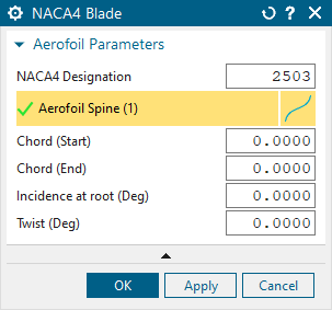
Single aerofoil section
All good aerofoils are designed on sections. For this example we first create a NACA4 aerofoil. We place the section in space on a co-ordinate frame, provide a total chord (how big it is) and set the NACA profile we want.

The custom feature runs a small bit of code whose single responsibility is to figure out aerofoil section co-ordinates. This result then gets transformed into the desired co-ordinate frame and we join the dots with a spline. Here is the finished result doing the lambada (or cycling through different NACA codes at least)
Build a solid aerofoil
What is an aerofoil if not a collection of aerofoil sections? The next custom feature does just that - places aerofoil sections (from above) along a spline and controls the properties of each section from some guiding parameters.
Note that all the user sees in the NX feature navigator is a single feature that wraps up all of this - but in the background the same code as in the section example is running to create each section up the blade.

Add an aerofoil root
Finally we need to mount the aerofoil on a root - a number of root styles exist in the world - but for this Custom Feature we create only axial and circumferential types. The GUI has one fixed area for shared parameters with a menu that changes depending upon which style of root you select - giving you specific parameters for that style.
The GUI contains validation code preventing the user from asking for silly things and ensuring that values fall within allowable ranges. Here it is being put through its paces.
|

|
|---|
Combine Aerofoil and Root Custom Features
I wouldn’t recommend designing a jet engine with these components just yet - but you can see how highly configurable custom features can give you a dramatic productivity boost inside NX whilst staying ‘designer friendly’.
Paul Booth